|
| Bevel Up |
|
| Finest abrasives. | ||
| Microbevels front and back. | ||
| Use a jig. | ||
| Copyright (c) 2002-15, Brent Beach |
This page is not setting out to prove whether or not bevel up planes work. They do work. This page sets out to discover if there are any sharpening problems particular to bevel up planes.
I think that you will see that the problem is quite subtle. If you sharpen well, you won't have any particular problems. If you don't sharpen well, the planes will fail to perform up to expectations. Sharpening well is more important for bevel up planes, especially low angle bevel up planes, than for bevel down planes. The fact that most people don't sharpen well may have held back the more widespread use of bevel up planes for finishing work.
A second consideration is the honing angle you chose. Most bevel up planes are used on end grain, so most people want to have a small honing angle. Some bevel up planes are used for specialized tasks. For example, people making fishing rods from bamboo usually use block planes. Bamboo is full of silica - it is very hard on plane irons. In this case, a more durable edge may be more important than a sharper edge. If so, a much larger sharpening angle may be better. The page that discusses camber on plane irons also discusses (with sketchup models) larger sharpening angles for bevel up planes.
Contents
In summary, friction with the wood wears the blade. This wear is confined to a very narrow region extending back from the edge. In experiments conducted on over 45 plane irons of many different makes, some irons tested several times, while taking over 1,300 images with the QX3, I have made some observations.
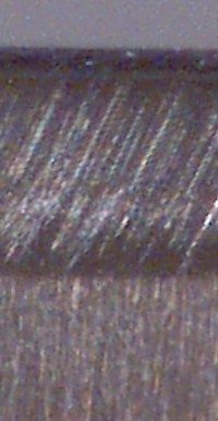
| Upper wear bevel |
|
| Lower wear bevel |
|
And this is the problem!
Conventional sharpening techniques handle the conventional problem: the problem of sharpening a bevel down iron. Conventional sharpening techniques concentrate on the bevel side of the iron. Conventional sharpening techniques do a good job on the bevel side, do little on the back face, but this works out pretty well for bevel down planes. The back face of the iron gets the upper wear bevel, which is slightly rougher than a well honed bevel and is at a slightly greater angle than expected. The net effect of not working the back face of the blade is a slight increase in effort, with little decrease in surface quality except perhaps for soft and stringy woods (where the increased effective planing angle is a negative).
With bevel up planes, the lower wear bevel is on the back of the iron. Standard sharpening techniques do not work the back of the iron enough to remove this wear bevel. Most jigs for sharpening irons do not even allow you to work the back face effectively while the iron is in the jig. The net effect is that the lower wear bevel remains on the iron after sharpening. While the edge seems sharp, the lower wear bevel is still wide enough to prevent effective use.
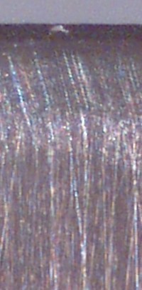
 The wood surface left by the plane now had a mirror quality. In this picture, we are looking down at a table top on which there is a steel ruler. The piece of wood is resting on a steel ruler, with the planed edge facing the top of the screen. The front face of the wood clearly reflects the ruler and the table top.
What happened here? What causes just planed wood to take on a polished look like this?
The plane is taking shavings, so the blade is cutting the wood. After cutting though, the blade is compressing the wood fibres. In effect, ironing the wood flat. The normally porous wood surface has been completely closed during this flattening. This wood will not readily accept any finish unless it is sanded first.
After discussing the shape of the worn bevel up blades, I will revisit, and try to explain, this problem.
With a bevel up plane you can increase the planing angle without changing the bedding angle if you increase the included angle. You can leave the primary the same and add a steeper microbevel. With a 12 degree bed, you get a 60 degree planing angle if the final microbevel is 48 degrees. The first series of tests compare the rate of wear bevel formation as a function of the included angle.
Block planes are bevel up planes that are used for planing end grain. Typically they use a small included angle and a small bedding angle which combine for a small planing angle. This small planing angle and the excellent blade support inherent in bevel up plane design are both helpful on end grain. Planes used on end grain get similar wear bevels.
|
In the first test, the blade had my standard bevels: a primary bevel at 25 degrees, then three microbevels on the front and back, with the first at 29, the second at 30.2, the third at 30.9 degrees. The back bevels are 2.4, 3.5, and 4.3 degrees.
Images are of worn blades, taken after 150 passes along the 4' Douglas-fir board. While performing well, this blade shows very high wear levels. This may in part be caused by the geometry - the low bedding angle means an initial low clearance angle. To be strictly comparable to results from bevel down planes with 45 degree blade bedding angle and 30 degree front bevel angle, we would need a bedding angle here of closer to 15 degrees. |
| |||||
| In the second test I increased the angle of the first front microbevel from 29 degrees to 34 degrees. The second microbevel was 35.3, the third was 36.4. Increasing the front bevel angle on a bevel up plane changes the effective planing angle. This has the same effect as changing the bed angle. Planes with higher planing angles can reduce tearout in highly figured woods. |
| |||||
| In the third test I increased the angle of the first front microbevel to 39 degrees. The second microbevel was 40.5, the third was 41.8. Adding the 12 degree bedding angle gives an effective planing angle of 53.8 degrees. |
| |||||
|
One problem with analysing these images is that the 0.5 micron abrasive leaves a surface that does not look a lot different from a wear bevel - both lack visible long scratches.
As an aid to analysis, I repeated test 3 with a slightly different sharpening sequence. First, 15 micron at 39 degrees as before. Second, 5 micron with the iron angled during sharpening and the jig resting on the 0.1" slider. No third microbevel. The final microbevel angles are the same as in the previous test; the final abrasive has changed. So, in this test the second and final microbevel is at 41.8 degrees. These pictures were taken after 150 passes along the 4' board. The last 10 passes were quite difficult - the plane wanted to skip along the board. |
|


The width of this wear bevel increases with increasing included angle. The larger the angle the more important it is that the back is restored to the desired bevel angle right up to the edge.
You have two ways you can handle this problem.
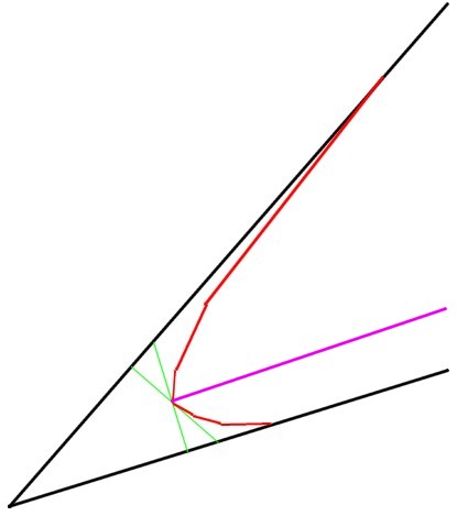
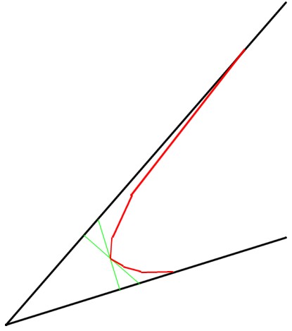 This drawing is a profile view of a dull plane blade in working position. It shows the last 0.01" of the blade. If you use my jig and the slips, the last 0.01" is the third microbevel. All blade wear take place in this very small region of the blade.
The outer black line is the profile of the sharp blade before use. In this case, the front and back third microbevels. If you use my jig you get perfectly flat microbevels, front and back, at the desired angle. The inner red line is the profile of a worn blade - showing the upper and lower wear bevels. The dimensions are based on micrographs of a plane blade in its just sharpened state before use, and it dull state after testing.
The upper wear bevel is long and flat, the lower wear bevel is short and steep. This picture is true for bevel up and for bevel down planes. The difference is that with bevel up planes, the short steep lower wear bevel is on the back of the blade.
In this discussion, we are considering only bevel up planes. That is, the upward facing bevel here is a front bevel. The downward facing bevel is a back bevel, or the back of the blade.
 First the bevel down case. In this image the bevel faces down and honing until the wear on the bevel side is gone is shown by the pinkish line. In the plane this blade is not really sharp, since there is still wear on the upper surface. However, the bevel side is as good as new. The blade has the original clearance and will plane fairly well.
 Now the bevel up case. In this image the bevel faces up and honing until the wear on the bevel side is gone is show by the blue line. This blade is just as sharp as the bevel down blade - it looks exactly the same. However, in the plane the lower surface still has all the wear of a dull blade. If you press the plane down hard enough, this blade will cut. But it will cut poorly.
The Lee Valley planes are very strong. Combined with the thick blade, you will be able to plane with a blade sharpened like this because the plane can transfer your downward pressure to the blade and drive it into the wood, even though it has a full lower wear bevel.
 If you use back bevels, you will create a new sharp blade that has a profile like the blue line. That is, you will remove some metal on the front and some metal on the back of the blade. You will completely remove both wear bevels.
This is an idealized result - the final microbevels ending at the tip of the worn blade. Honing has not shortened the blade at all. You will probably not get this result. In fact, I don't even try for this result. It is the easiest result to draw however.
When I hone, I aim to achieve this blue line on the first microbevels. I hone the front on 15 micron abrasive until the scratches reach the edge - the old front wear bevel is gone. Then I hone the back on 15 micron abrasive until the scratches reach the edge - the old back wear bevel is gone. This would be approximately the situation in the drawing. The wear bevels are removed completely by the 15 micron abrasive.
The second and third microbevels shorten the blade, while retaining the same basic geometry.
The problem with back microbevels is that these bevel up irons are often short, some very short. Say you have a 4" blade and get get a 3" extension of the edge from the jig. If you use a jig like mine, where the thin jaw is 1/8" wide, the extension calculator produces the following results:
| Inputs | tall jaw height | 1.5 | inches |
| short jaw height | 0.125 | inches | |
| short slip height | 0.06 | inches | |
| tall slip height | 0.10 | inches | |
| jaw angle | 90 | degrees | |
| blade thickness | 0.075 | inches | |
| bevel angle | 29 | degrees | |
| Outputs | Extension | 2 + 27/ 32nds | inches |
| Base of jig to blade | 3.1 | inches | |
| Actual angles | |||
| ... no slip | 29 | degrees | |
| ... short slip | 30 | degrees | |
| ... tall slip | 30.7 | degrees | |
| Back bevel angles | |||
| ... no slip | 2.5 | degrees | |
| ... short slip | 3.7 | degrees | |
| ... tall slip | 4.5 | degrees |
Notice the final back bevel angle is 4.5 degrees. This reduces the clearance from 12 degrees down to 7.5 degrees.
A better honing strategy might be to not use the slips when honing the second and third back micro bevels. You sacrifice the quality of the surface, but gain 2 degrees of clearance. I suspect the trade-off favours omitting the slips for the back bevels. You might spend a little longer on the second and third grits to make up for using the same angle.
 If you work only from the front, you must grind/hone down to this blue line. That is, you must shorten the blade by the length of the back wear bevel.
When during honing your new front bevel reaches the dull edge, you have visually removed the front wear bevel. You can no longer see a bright line at the edge, when looking at the bevel. People may well stop honing at this point. The entire back wear bevel is still present.
If you continue honing the front bevel until you can feel a wire edge, you may still have not removed the entire back wear bevel. You will start to feel a wire edge as soon as you hone through the dull edge.
Another alternative is to just buff the back of the iron using a charged leather strop. I discuss stropping here. While stropping may smooth the rounded back wear bevel a little, it will not flatten it. That is, it won't create a flat back bevel at the edge that is roughly (within 3 or 4 degrees) co-planar with the back face.
My answer - The above discussion points out that people using bevel up planes should be a little more conscious of the condition of the back of the blade during sharpening than those using bevel down planes. I am not saying that sharpening won't remove the entire back wear bevel, just that it might not.
When working the front bevel you can raise a wire edge without removing the entire back wear bevel. As soon as the abrasive reaches the edge, it starts to create a wire edge. So, the presence of a wire edge is not enough to ensure that you have removed the entire wear bevel on the back face.
If you use my jig and work the first microbevel at 29 degrees until the scratches reach the edge, then at 31 until the second microbevel is 0.01" wide, you only shorten the blade by 0.0006". The third microbevel shortens the blade by about half of that again, for a total of less than 0.001". You have shortened the blade by about half of a wide back wear bevel. So, if you are using bevel up blades and my jig, be sure to raise a good wire edge on the 15 micron abrasive, then continue as usual.
I don't know how much metal the average user removes when sharpening a blade. In fact, I have never actually tried to determine the amount of metal lost when going from a dull blade to a sharpened blade. I have only begun using scribe marks on blades to make sure I get the same part of the blade in each image. I usually mark the blade after the first abrasive - which may have shortened the blade already. These scribe marks allow me to determine how much metal is removed by the second and third microbevel, when done on both sides.
I will get some pictures to show the shortening of a plane blade (both bevel up and bevel down) in upcoming tests and add a section to the FAQ page.
 This google model shows the honing microbevels and the wear bevels for a blade used bevel up. Notice, as mentioned many times, that the wear bevel occurs entirely within the third micro bevel. All other honed bevels never make contact with the work in a way that affects their surface. Equally important, this means that the smoothness of the other honed bevels does not matter - either in the resulting planes surface or in the durability of the tool.
 This model shows what happens as you hone the first microbevel on the front face. The left half of the upper face retains the former bevels, the right half shows the new bevel. There is still a bit of wear bevel visible from the front side (a very small amount).
You cannot get a wire edge during this part of the honing because the metal at the edge is still well supported by a thick piece of metal. The metal at the edge cannot flex back away from the abrasive and be retained as a burr.
 Here the first micro bevel reaches the edge. Wear is no longer visible from the front. Even using a microscope, this blade would look sharp from the front.
As you can see, all of the wear on the back face is still present. Honed this way the blade would seem as dull as it was before this honing session.
Additional honing now can produce a wire edge because the metal at the edge no longer has any metal behind it for support. If you use the presence of a wire edge as a signal to stop honing, you would still be honing at this point.
 This model includes the second front microbevel, shown by the yellow surface.
Honing a microbevel continues until the new microbevel is about half the width of the previous microbevel. With experience you will discover how long this takes. In my experience, 15 to 30 seconds.
The back face still contains much of the wear bevel. In use, this blade will seem a little sharper, but certainly not like a really sharp blade. That is, a blade with no lower wear bevel.
 This model includes the third front microbevel, shown by the blue surface.
I have zoomed in on the part of the model in which the amount of metal removed is clearest. The first microbevel (green) removes the greatest depth at the edge. The second almost as much. The third, almost none.
Most of the lower wear bevel is still present. This blade would not feel sharp but is not as dull as before honing.
 This model continues the honing of the first front micro bevel until all the wear bevel is gone on the back face. This blade is now sharp. [I had to extend the model a bit because the first micro bevel is now so wide.]
The time taken to hone this bevel is proportional to the amount of metal removed. That is equal to the area of the green face here times the depth of metal removed times the width of the blade.
Using areas from this model and the second model up, in which the first micro bevel stopped at the edge, the difference is a factor of 3.73. Instead of spending 1 minute on the first microbevel, you spend almost 4 minutes. [Use up your abrasives almost 4 times as fast, ...]
Instead of saving time by honing only one face, you end up spending more time.
As well, the first microbevel is about 50% wider. This means you have to grind 50% more often.
 This model is derived from the earlier model - front only sharpening, after the half micron abrasive. I have shown the entire blade with this sharpening and put it on a piece of model wood. A blade prepared without microbevels but only sharpened from the front to the same extent would produce the same result.
From the front, this blade looks sharp. The last microbevel is uniform and flat right up to the edge. The finger nail test would find no catches. A check from the back would show the wear bevel though - a bright line along the edge in appropriate lighting.
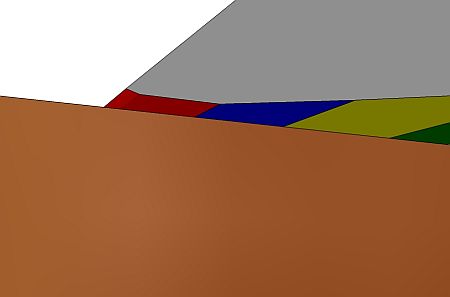 In this closeup of the blade, I have moved the point of view under the blade and pushed the wood to the side so you can see that the lower wear bevel (in red). Part of the lower wear bevel is resting on the wood, part is above the wood, between the edge and the wood. Right now this blade will not cut the wood.
However, if you push down hard you will compress the wood enough that the edge is in the wood. The blade will then cut.
The downward force you are exerting is focused on the blade near the edge. With a thick enough blade, a strong enough plane, and a hard enough wood, the force on the edge will cause the edge to break. That explains the first part of the woodworker's experience - edge failure.
The downward force on the wood behind the edge burnishes the wood. It crushes the wood fibres down into a smooth surface. This is similar to what happens in wood mill when they dimension lumber. They use big planers with less than sharp edges. The planers do remove wood but they also pulverize the wood surface, burnishing it in the process. Whether or not this glazing affects the ability of a wood finish to adhere is controversial. However, it does affect the appearance of the wood. This would be particularly apparent with a clear finish.
The modified sharpening protocol discussed next removes all of the lower wear bevel. As a result, it eliminates both of the problems discussed in the current section. A new sketchup model showing a blade sharpened according to the modified protocol resting on a piece of wood makes this clear.
In this, protocol which is particular to bevel up planes with low bedding angles, the slips are not used when honing the back face. The result - there is only one back bevel and it is about 2 degrees. A 2 degree back bevel combined with a 12 degree bedding angle leaves a 10 degree clearance angle. A larger clearance angle means the plane does not appear to be dull until the edge is much duller.
The problem with using only one bevel angle on the back is that the finer abrasives work very slowly on wide bevels. We deliberately keep the bevel on the back very narrow.
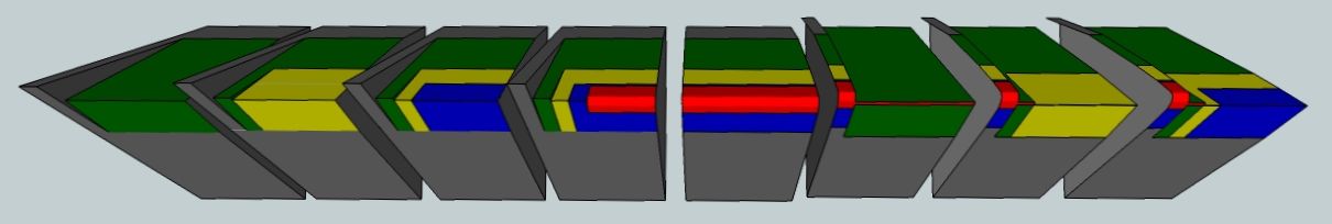
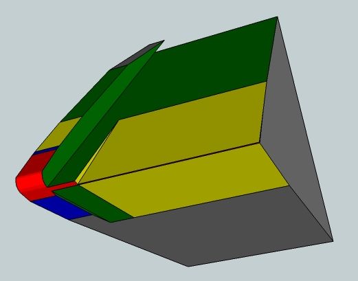
This first picture is the whole series of 8 models which take you (working left to right) from
All the models are shown with width 400 pixels, although some are larger than that. Copy the image into a graphics program to see the larger image.
 The blade is shown bevel up. The outer grey shows the original primary - 25 degrees on the front, flat back.
The green shows the first front and back honed microbevels. These are produced using the jig without slips. The front bevel angle is 29 degrees, the back about 2 degrees.
The front microbevel is the usual width - the width that ensures that enough metal is removed at the edge to go past the metal deformed during grinding.
The back microbevel is quite narrow, only a third of the width of the first front microbevel. We must keep this narrow because we will be honing at exactly the same angles with the two finer abrasives. Keeping this microbevel narrow means that the next abrasives will be able to remove enough of the surface metal to ensure a flat smooth second side to the edge.
 The yellow shows the second front and back honed microbevels. The front is produced using the jig on the thin slip, the back with no slip. The front bevel angle is 30 degrees, the back is 2 degrees.
The second abrasive, I use 5 micron, does not remove enough metal to greatly increase the width of the lower microbevel much.
 The blue shows the third front and back hone microbevels. The front is produced using the jig on the thick slip, the back with no slip. The front bevel angle is 30.6 degrees, the back is 2 degrees.
Again, the third abrasive, I use 0.5 micron, does not remove enough metal to change the width of the back microbevel much.
With the iron bedded at 12 degrees and a back bevel angle of 2 degrees, the clearance angle is 10 degrees.
 This model shows the worn edge.
As usual, the lower wear bevel is short and steep and the upper wear bevel is long and shallow.
The problem, is mentioned before, is that the short steep bevel is on the back of the blade. Normal sharpening up to the edge has no effect on this wear bevel.
It is the lower wear bevel that causes the plane iron to appear dull. As you push the blade forward, the blade tends to lift up as it surfs along the wood.
 Again, with the wear bevel across the blade. I made this model as the first step in the series of models of honing a worn blade, so include it here.
 We begin the process of sharpening, but from a dull blade this time.
Honing the front with no slip at 29 degrees, the back with no slip at 2 degrees.
Most of the metal removal takes place when honing the front with the first abrasive. This step removes the previous honed bevels and most of the wear bevel on the front and back.
Very little metal is removed on the back - just a slight narrowing of the wear bevel.
 Honing front and back with the second abrasive very nearly removes the wear bevel.
Honing the front with the thin slip at 30 degrees, the back with no slip at 2 degrees.
 The final sharpening step - the third abrasive. Honing the front on the thick slip at 30.6 degrees, the back on the thin slip at 2 degrees.
The blade is not the same in the part of the blade that makes contact with the wood as it was after the last sharpening. The honed bevel on the back is intended to be exactly the same - it should not widen from one sharpening to the next. The first honed bevel on the front widens with each honing. Eventually, after 3 to 5 honings, it is wide enough that honing with the 15 micron abrasive takes quite a long time. It is time to regrind the front. The back is never reground.
Of course, the model presents an ideal result - the third microbevels meet just as the wear bevel disappears. An ideal result, but not an essential result. Typically, you would take off a little more than this. That is not a problem.
The goal is to have the second and third microbevels on the front about the relative widths you see here.
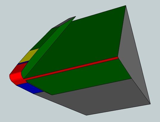
 This model is derived from the immediately preceding model. I removed the bits at the side which show old bevels and added a piece of model wood. The blade is bedded at 12 degrees but now has a single flat lower microbevel. The honing operation, as explained above, removes all of the old wear bevel.
The blade is positioned so we can see the lower honed microbevel and the contact the blade makes with the wood. Before the contact was across the old wear bevel. Now the region of contact is confined to a very narrow line right at the edge. Only a very small downward force is required to push this edge into the wood. [Of course, if you increased the set and pushed really hard you might be able to break the edge.]
This blade slices off a shaving without burnishing the wood surface. No broken edge, no burnished wood.
David Dack, who reported the original problem, has done some more testing. He sharpened an O1 steel blade (25 degree primary, 29/31/32 degree microbevels) for the same plane taking care to remove back wear. He then planed the same piece of wood with downward pressure only on the toe of the plane, forward pressure on the tote. He reported finer shavings with no undue blade chipping or wear.
Return to the Sharpening home page.